
By Josh Wardell
Junior Design Project April 1999
Construction
By Josh Wardell
Junior Design Project April 1999
Construction
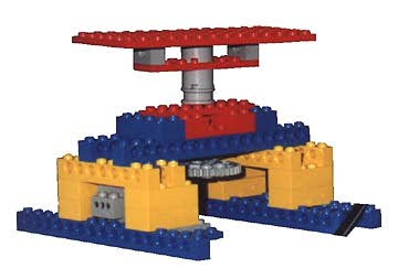
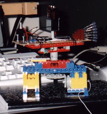
I will first start with the construction of the Lego assembly, as this may be the simplest part. Various common Legos were used to build something that was sturdy so that any wobbling would be at a minimum. Legs on the bottom gave it a large bottom surface area so as not to tip. At the top, the spinning axle was secured to the assembly at several points to reduce any motion that a perfect spin, as that would add extra torque to the motor. The standard Lego motor was used, with its axle on a horizontal axis. It was powered by an external power supply, variable to vary the speed of rotation. A 90° gear was used to adapt it to the vertical axis of the main axle. The largest Lego gear was used so that a maximum amount of rotational speed could be obtained. The main axle was fixed to the top Lego board, to which the electronics PC board would be attached. The best way to duplicate this is simply to reference the picture below:
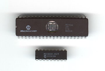
1 Microchip® PIC 16C84 microcontroller 1 74HC241 7 T 1 1/2 diffused blue LEDs 7 47 W resistors 1 7805 5V voltage regulator 1 9V battery 1 PC board 1 various Legos® including motor and gears 1 PC with PicStart Plus programmer and MPLAB programming software 1 variable power supply (‰6V, 500mA)
The assembly code is attached at the end of this report. To explain simply, the lower 7 bits of Port A were used as outputs, one for each of the LEDs. This port direction and timers were initialized. The chip was then thrown into a continuous loop to display the message. The message is displayed by jumping to a subroutine for each text character to be displayed. These subroutines passed values into the port to turn on or off each LED for each column to be displayed (this is passed in binary and therefore it is easy to see the actual characters in the code if you look at the 1's and 0's sideways). Between each column a delay loop was run so that the LEDs would stay on for a certain amount of time. The code in reality stepped linearly though each column of pixels for each character in the text message. Note the code attached displays my name, "Josh W."
Next is the assembly of the PC board and the electronics. If you are a perfectionist at soldering like me you will need to set aside four hours for this. Note the attached schematic for connections and placement. All components were attached with DIP sockets so they were reusable, including the LEDs, which were in a 90° DIP socket to mount them vertically.
Because this board is rapidly spinning there is no way to get power up to it without some kind of complex rotational contacts so a battery is needed to power it. Because everything on the board needed a minimum of five volts and stacking up a bunch of AA batteries would add unneeded weight and mounting complexity, I decided to use a single 9V battery. This was attached with a standard 9V battery clip, directly centered on the axis of rotation so its relatively large mass would not cause the board to wobble.
All components operate at +5V TTL levels, so a 7805 voltage regulator was used to bring the +9V of the battery down to a perfect +5V. This also allows for the battery to vary in voltage as is common throughout its life; in my experimenting it still operated with a voltage of merely 5.5V. The resistors for the LEDs were also adjusted to give approximately 15mA per LED at this voltage, and the value that brought me closest to this in my case was 47W. Note that blue LEDs are new and therefore inefficient; they have a much larger voltage drop that most other LEDs, and at the same time are more sensitive, so I gave them 15mA instead of the suggested 20mA.
A four MHz TTL oscillator was used, which is a common clock speed for my microprocessor, although it can support up to 10 MHz. Speed is not needed, however, as most of its time is spent in delay loops, so a slower speed is more ideal as well as more stable.
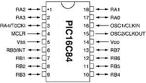
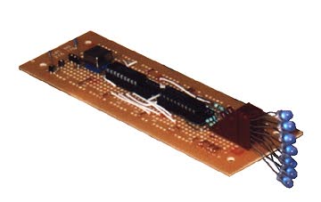
Another main chip used in addition to the microcontroller was the 74241 gate. This chip can be configured to do a few different tasks but in this case was just configured to be a gate. The I/O ports of the µcontroller do not support enough current to drive the LEDs. Instead of using several transistors, the 74241 was a simple, compact component that serves the same purpose. It can drive its outputs at about 20-25mA, so it was perfect for this purpose. It was configured simply to make the output high if the input was high. Refer to the attached schematic for its pinout. All assembled (without the battery), the board appears as pictured below:
Top - Introduction - Conclusion - Schematics - Source
Home - About - Email