For 2005, John Cooper Works introduced an intake for the MINI that is unlike any other. Over 4500 rpms, a flap opens to allow extra air in through the windshield cowl. It is available as an upgrade to the full Works kit as I have, but also on its own for any model MINI. It adds the performance of most other aftermarket intakes, but keeps the heat and weather protection of the stock airbox. Despite the air filter being second to oil changes as a common self-maintainance item, no instructions are offered to change the filter yourself. This shows how to do so, and also explores how this complex intake system works.
Parts:
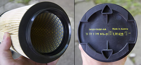
(1) Replacement JCW cylendrical air filter 13-72-0-392-826 $99.00us
Tools:
Torx25, flat-head, and phillips screwdrivers, pliars
Time:
10 mins
Changing the filter
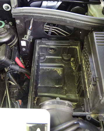
1. Disconnect everything from the airbox. From the top, counter clockwise:
- Electrical connector to vacuum valve: squeeze metal bar behind and pull.
- Positive battery terminal: Pull up and off, then push left off its post
- Vacuum line to engine: Pull hose at connection
- Upper airbox output hose: Use a flathead screwdriver to twist and pry metal ring to pop open. Slide back and pull rubber hose off airbox.
2. Unscrew the two Torx 25 screws at the front until they are loose (they are captive). Push the whole airbox top back about a half inch, then pull up and remove.
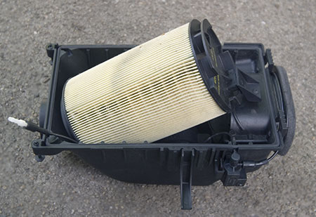
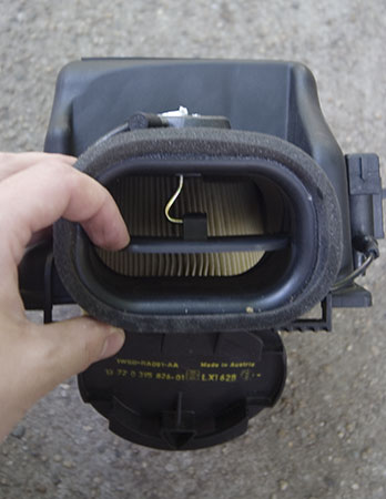
3. Inside there is a small bracket holding the filter on. Unscrew the philips screw. Remove the bracket. Then pull off the filter.
4. Insert the new filter and reassemble everything. Make sure the back tabs are caught when replacing the airbox top; push back and down, then slide forward. Check the airbox seam with you finger to make sure it is properly seated. Use pliars to squeeze the metal clip back together around the intake hose. Don't forget the small engine vacuum line!
How it works
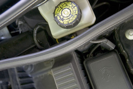
The JCW intake appears to be electronically controlled but vacuum-powered. This photo shows the vacuum line from the engine comes in from the bottom, to a (removed from inside) vacuum cylinder, then to a electrically-controlled valve. Then from the valve to the vacuum piston that lifts and opens the flap.
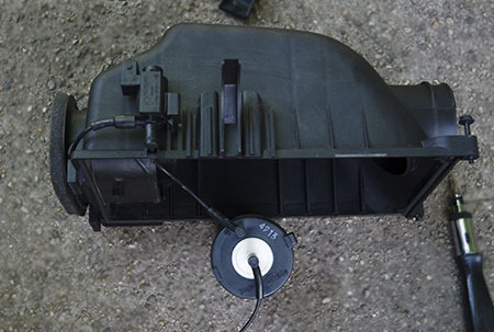
The electronic control box has a positive wire to the fusebox, ground wire, and a yellow engine signal wire that goes into the engine CPU. When it sees teh engine rev over 4500rpm, it sends 14V to the vacuum valve.
It may be possible to override the system by tapping the connector to the vacuum valve and switching it on manually for racing purposes, however the flap will not open until there is enough vacuum to do so. I may experiment with that in the future.